
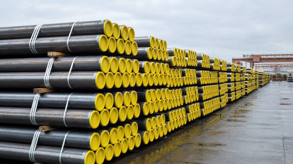
Casing vs Tubing: What Are Their Roles in Oil and Gas Wells?
One casing or tubing mis-specification can stop a well programme before first production. Most purchase orders are still copied from a previous job rather than engineered.
Casing is the larger steel pipe cemented permanently in the borehole to seal formations; tubing is the smaller, retrievable pipe run inside the production casing to carry oil and gas to surface. Casing is structural; tubing is the flow conduit and can be pulled for workovers.
Transition: the two products sit on the same pipe rack, are ordered from the same mill and often share the same grade, yet they are designed against completely different failure modes. The sections below follow that sequence — what each string is, how their designs diverge, which standards govern them, how connections and sizes are selected, and what inspection has to prove before either string leaves the yard. Read it in order and you will be able to tell a casing enquiry from a tubing enquiry at a glance.
What Are Casing and Tubing, and Where Does Each Sit in a Well?
Casing lines the borehole; tubing hangs inside the last casing string. Both are steel pipe, and both belong to the same product family.
Casing is steel pipe run and cemented inside a drilled hole to support the borehole and isolate formations from one another. Tubing is steel pipe run inside the production casing, sealed at the bottom by a packer, to convey produced fluid to surface.
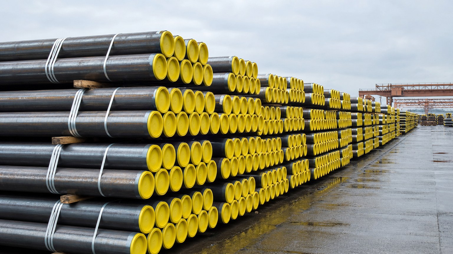
The casing hierarchy, from conductor to production string
The nesting logic is the point. As described for well casing, casing is a large-diameter pipe assembled and inserted into a drilled section of borehole, with the lower portion cemented in place, and a typical well contains several intervals of casing set successively inside the previous run. The hierarchy normally runs conductor, surface, intermediate, production casing and, where a full string is uneconomic, a production liner hung off downhole instead of at surface.
Each string earns its place. Conductor casing is set shallow to support loose surface formations and to return drilling fluid while the next string is drilled. Surface casing isolates freshwater zones so they are not contaminated during drilling and completion, which is why it is the most strictly regulated string on the well. Intermediate casing is run where pore pressure and fracture pressure diverge far enough that a heavier drilling fluid is needed to keep the well under control. Production casing is the final full string: it isolates the producing interval, which is then perforated selectively, and its inside diameter has to accommodate everything that will later hang inside it.
Where tubing fits into the completion
Tubing arrives last. Few wells actually produce through casing, because produced fluids corrode steel, deposit paraffin and scale, and a large bore makes flow unstable. Tubing is therefore run inside the final casing string, and a packer seals the annulus at the bottom of the tubing so formation fluid cannot travel up the outside of the pipe. Because tubing is significantly lighter than casing and is not cemented, it can be pulled and re-run with a service rig rather than a drilling rig — a decisive cost difference every time a well needs a workover. For the wider product family, our recent guide to oil country tubular goods sets out how casing, tubing, couplings and accessory material are ordered together.
How Do Casing and Tubing Differ in Function and Design?
Casing is designed for the worst load the well will ever apply; tubing is designed for flow and for being pulled and re-run.
Casing is specified for burst, collapse and tensile capacity because it is permanent and cemented. Tubing is specified for a pressure-tight, repeatable connection and a smooth bore, since it must be pulled for workovers.
Load cases that drive casing design
Every casing string is designed as a pressure vessel rather than as a pipe. The design engineer calculates the worst combination of conditions the tubulars will meet while drilling and throughout the producing life of the well: collapse resistance against external pressure deeper in the hole, burst resistance against internal pressure nearer surface, and tensile capacity to carry the weight of the string when it hangs in the wellhead. Axial and hoop stresses interact, so the requirement shifts with depth — the upper part of a long string usually carries the greatest tension and the highest burst differential, while the lower part carries the highest collapsing load. That is why one string is often made up from more than one wall thickness or grade. Because casing cannot be inspected or replaced once it is cemented, the design margin is fixed for the life of the well, and every later decision — perforating, stimulation, gas lift, artificial lift — has to live inside margins chosen years earlier.
Why tubing is specified for repeatability
Tubing is designed to be removed. The functional requirements therefore move away from structural strength and towards flow assurance and repeatability: a smooth bore that does not restrict production, a connection that stays pressure-tight after being made up and broken out many times, and resistance to the specific produced fluid, whether that means carbon dioxide, hydrogen sulphide, chloride-rich brine or simply sand-laden crude. As noted for production tubing, the string protects the casing from wear, corrosion and deposition of by-products while providing a continuous bore from the producing zone to the wellhead, and its purpose and design exist to make installation, removal and reinstallation quick, efficient and safe. Most casing and tubing in this family is produced as seamless pipe rather than welded, because a pierced wall leaves no seam to interrogate in a service where a seam defect becomes a well-control event. Our overview of casing vs tubing in seamless form sets out the size and wall range available on that route.
Which Standards and Grades Apply to Casing and Tubing?
One specification covers both products, which is precisely why buyers confuse them.
API Specification 5CT, matched internationally by ISO 11960, sets the technical delivery conditions for casing, tubing, pup joints, coupling stock and accessory material, including grades, product specification levels and testing. Threads are covered separately by API Spec 5B.
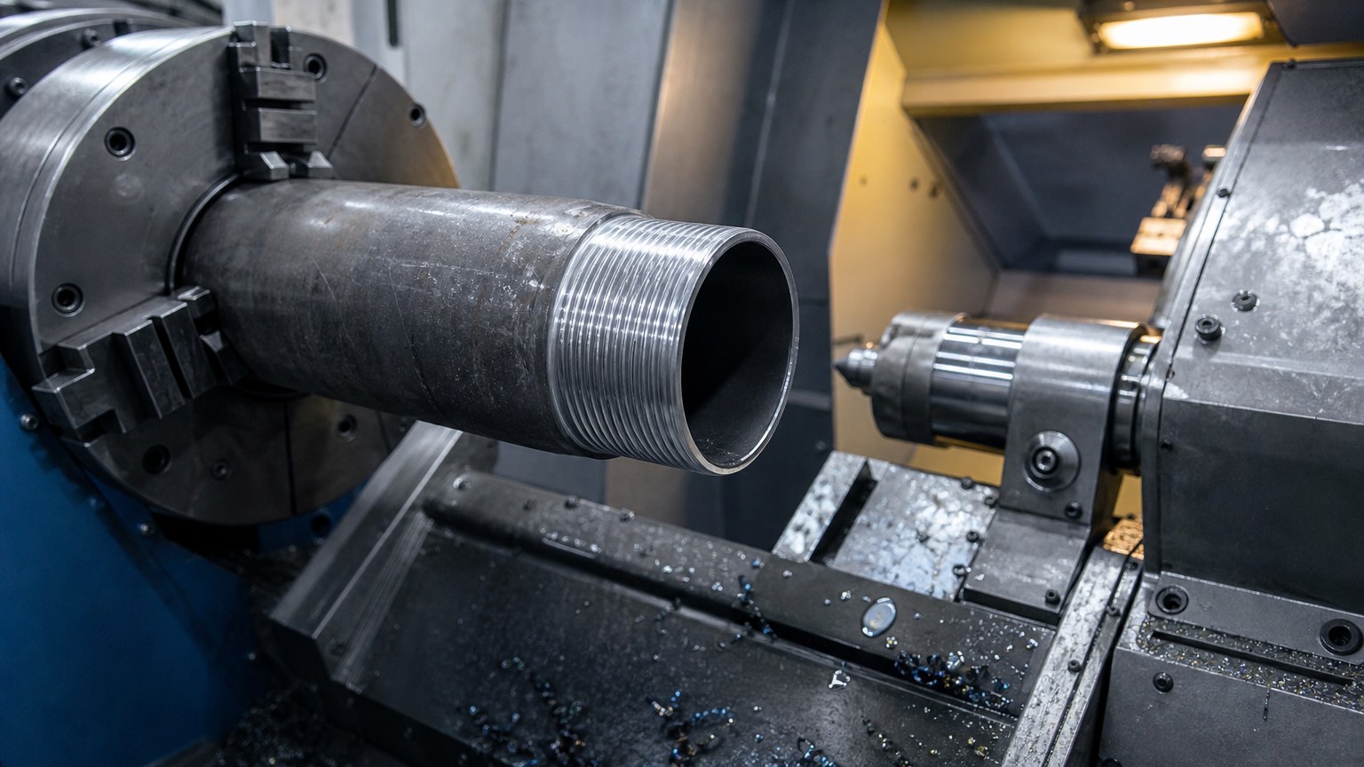
What the grade number actually means
The ISO 11960:2020 standard page lists the grades the document applies to: H40, J55, K55, N80, L80, C90, R95, T95, P110, C110 and Q125. The letters group the pipes by strength and by service, and the number is in most cases the specified minimum yield strength in ksi — roughly 55 ksi for J55 and K55, 80 ksi for N80 and L80, 110 ksi for P110. Beyond strength, each grade carries a heat-treatment condition, and the sour-service families carry hardness ceilings as well, because sulphide stress cracking is a hardness-driven failure rather than a strength-driven one. A suffix such as 13Cr indicates a modified chemistry chosen for resistance to carbon dioxide, which is a materials decision rather than a strength decision. Grade requirements are not static: the API Specification 5CT page records that the 10th edition eliminated grade M65 entirely, updated N80 Type 1 requirements, added polymer quenching for L80, revised hardness requirements for L80, C90, T95 and C110 as a result of NACE MR0175, and replaced the old supplementary requirement for test certificates with new mill test report requirements.
Grades and product specification levels are not interchangeable
Two quotations for the same size, wall and grade can differ substantially without either supplier being dishonest, because they may not describe the same product specification level. PSL-1 is the baseline and is normally adequate for straightforward service strings. PSL-2 adds mandatory non-destructive examination together with tighter chemistry and impact-testing requirements, and it is the usual basis for pressure-critical or low-temperature service. PSL-3 goes further for the most demanding sour and high-pressure applications. The practical rule for a purchaser is to treat grade and PSL as two separate specification lines on the enquiry, never as one, and to state the standard edition the order is placed against. A quotation that answers only the grade question leaves the most expensive variable — the inspection and testing regime — completely open.
How Are Connections Different for Casing and Tubing?
Strength stops the pipe failing; the connection decides whether the string holds pressure.
Casing typically uses short or long round thread or buttress thread, while tubing uses non-upset, external-upset or integral-joint connections. Premium gas-tight connections are specified where high pressure, gas and cyclic load combine.
API thread families and their limits
Round thread casing is the oldest and most widely available family, and its constraint is geometric: the thread form depends on interference and on a thread compound to seal, so its pressure integrity is limited and it suits lower-pressure service or applications where a small leak path along the thread is tolerable. Long round thread spreads the load across more engaged turns and is preferred where the joint carries higher tensile load. Buttress thread casing changes the profile to a near-vertical load-bearing flank, which raises joint strength and is the conventional choice for heavier intermediate and production strings where the connection, not the pipe body, would otherwise be the weak point. Tubing follows the same logic in a smaller envelope. Non-upset tubing leaves the tube plain and needs couplings, external-upset tubing thickens the pipe ends to recover the strength lost to threading, and integral-joint tubing machines the connection into a thickened wall so the outside diameter stays as small as possible — useful where clearance inside the completion is tight.
When a premium connection is genuinely required
Premium connections exist because gas-tightness under combined load is a different requirement from tensile strength. They are usually specified where three conditions meet: high pressure, the presence of gas rather than liquid only, and load cycles that include bending from directional drilling. The design features that answer those conditions are a metal-to-metal seal instead of a thread-compound seal, a torque shoulder that controls make-up precisely, and often a tapered or wedge thread for faster running and better resistance to over-torque. The selection sequence is therefore not cosmetic: define pressure and temperature, decide whether gas-tightness is mandatory, estimate the bending and cyclic loads the string will see during installation, then compare the resulting requirements against what the standard threaded families can demonstrate. Where the API families cannot prove the required performance, a premium connection is the honest answer rather than a heavier wall. A small tubing string is where this becomes most visible in practice: 2-7/8 inch J55 OCTG tubing is a common completion size, and the connection specified with it decides whether the string qualifies for the pressure and cycle count in front of you.
How Do Sizes and Weights Differ Between Casing and Tubing?
Casing and tubing are both quoted in inches, yet the two size series barely overlap and are ordered against different tables.
Production casing commonly ranges from about 4-1/2 to 9-5/8 inches, liners are frequently 7 inches, and tubing is the smaller conduit run inside the last casing string, typically from around 2-3/8 up to 4-1/2 inches, with wall thickness expressed as weight per foot.
Why the two size series cascade instead of matching
The reason casing and tubing sizes do not line up is geometric and non-negotiable. Every hole must be drilled large enough to accept the casing and still leave an annulus for cement, and every subsequent bit must pass through the casing already in the ground, so each string is one size step smaller than the one above it. By the time the production casing is set, the inside diameter left over for the tubing, the packer, gas-lift mandrels and subsurface safety valves is a fraction of the original hole size. Two practical consequences follow. First, casing is bought against a size and weight range, because the outside diameter and wall thickness are what the cementing and clearance calculations actually use. Second, tubing is bought against an inside diameter, because the bore is what governs flow and what the completion tools must pass through. A buyer who quotes both from a single size list will normally end up with one of the two wrong.
| Attribute | Casing | Tubing |
|---|---|---|
| Primary role | Support the borehole, isolate formations | Convey produced fluid to surface |
| Installed position | Cemented in the drilled hole | Hangs inside the production casing |
| Typical size range | About 4-1/2 to 20 inches and larger | About 2-3/8 to 4-1/2 inches |
| Removable? | No, fixed for the life of the well | Yes, pulled with a service rig |
| Connection families | Round thread, buttress thread, premium | Non-upset, external upset, integral joint, premium |
| Design driver | Burst, collapse, tensile capacity | Flow, gas-tightness, repeat make-up |
How weight per foot is used in practice
Wall thickness in this product family is normally expressed as weight per foot, which is a nominal figure that combines a specific outside diameter with a specific wall. The same nominal size therefore exists in several weights, and each weight gives a different inside diameter, a different drift requirement and a different collapse and burst rating. That is why a request for seven inch casing without a weight is not a specification, and why substituting a heavier weight for a lighter one without re-checking the clearance and the connection is a common and expensive error. Buyers importing on a first order should ask the mill to confirm the weight basis, the drift diameter and the length range on the enquiry return, because those three values decide whether the string will pass the completion tools. Shuncheng Steel supplies seamless casing and tubing to imported size and weight requirements, and confirming the weight basis in writing before booking keeps the specification unambiguous on both sides.
How Should You Specify and Verify Casing and Tubing Before Buying?
The well decides the specification; the mill certificate and the gauges prove the pipe.
Specify pressure, depth, fluid and load case first, then fix grade, PSL, wall thickness and connection as one system. Verify dimensionally, metallurgically and at the connection, and match all three to the certification.

Specify the well before the product
Most specification failures in this product group start in the wrong order: a size and grade are copied from a previous project, and the well conditions are checked afterwards. The stronger sequence is to define the well first — maximum pressure, total depth, produced fluid chemistry, temperature and the installation load case — and only then select grade, PSL, wall thickness and connection together, because each of those four constrains the others. A sour-service grade may force a hardness limit that rules out a stronger grade; a heavier wall may rule out the connection that was originally quoted; a premium connection may remove the need for extra wall in the first place. Because this is the stage where the well is completed and production begins, the connection and completion design should be reviewed as one document rather than as two separate purchases. Where the well programme is still being finalised, it is cheaper to have the mill confirm what is available for each option than to change the order after the material has been rolled.
The verification sequence that protects a buyer
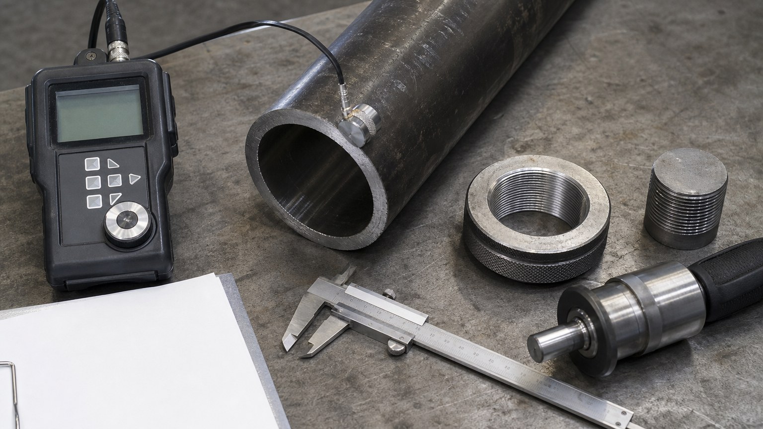
Inspection should be built in the mill’s own sequence rather than invented at the load port. Start with the pipe body: a wall thickness survey around the circumference and along each sampled length quantifies the eccentricity that the piercing route inherently produces, and it protects the burst and collapse calculations directly because those equations use minimum wall rather than average wall. Drift testing confirms that the bore will pass the tools the completion requires. Then metallurgy: chemistry and tensile tests, hardness surveys and, where the grade or the service calls for it, impact tests at a specified temperature. Finally the connection, which is where this product family differs most sharply from general pipe: thread form, taper, pitch diameter and standoff must be gauged with the correct API gauges, thread protectors must be fitted, and make-up torque must be controlled. A pipe that passes every body test and fails thread gauging is still an unusable joint.
Documents, marking and the handover checkpoint
Three habits prevent most claims. First, require the heat number to be transferred to each length or bundle, so that certificates can be matched to material rather than to a delivery note. Second, require the certificate to state the standard and edition, the grade and product specification level, the wall thickness or weight basis, the heat-treatment condition and the connection type — and treat anything shorter as an incomplete document set. Third, where the order value justifies it, appoint a third-party inspector and witness the gauging, the wall thickness survey and the hydrostatic test at the works, because that is the moment when a re-test is still inexpensive. Before loading, confirm piece count and length against the packing list, photograph the thread protectors and coupling condition, and check that marking is legible on the material rather than only on the paperwork. If you want the grade, PSL, connection, weight basis and certificate set agreed before production starts, send your well programme to our export team and we will confirm what is available against the service conditions you describe. For context on how casing and tubing sit inside the wider completion sequence, the overview of well completion is a useful starting point.
Conclusion: Which String Do You Specify, Casing or Tubing?
Casing seals and supports the well; tubing produces it. Specify each against its own load case, then prove both with traceable inspection.