
Rebar Lap Splice Length: How Do You Calculate It for HRB400 Rebar?
Specifying a lap splice by habit instead of by calculation is one of the most common — and most expensive — reinforcement errors in export construction projects.
Short answer: lap splice length is a multiple of the bar diameter. For HRB400-class deformed bar in tension, international practice commonly falls between about 40 and 50 bar diameters, with shorter multiples permitted in compression and where confinement is good; the governing value always comes from the project’s design code.
Reinforcement detailing is where a good bar specification either pays off or falls apart, and lap length is the single number that most often decides it. This guide breaks the calculation into its parts, shows what pushes the required overlap longer or shorter, compares how the main standards treat splices, and ends with the checks that catch problems before concrete is poured.
What Is a Rebar Lap Splice and Why Does Length Matter?
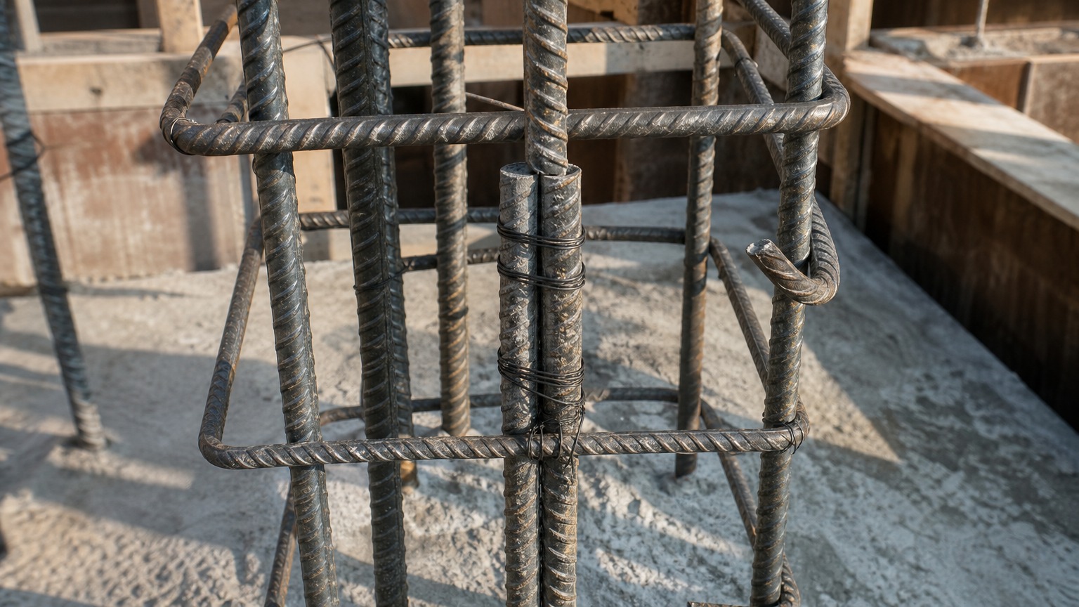
Two bars overlapped and tied are not yet a splice — the overlap only performs as a splice when it is long enough for the concrete to grip both bars.
A lap splice is an overlap between two reinforcing bars that is long enough for bond and rib bearing to develop the bar’s strength, so force can pass from one bar into the other without slipping.
How force crosses a lap splice
The mechanism is mechanical, not adhesive — it is the same bond that allows reinforced concrete to carry tensile force at all. As concrete cures it shrinks onto the bar, and when the bar is pulled, its rolled ribs bear against the concrete in front of them. That bearing — not surface friction — carries the load. In a lap, force entering the first bar transfers into the surrounding concrete across the overlap zone and re-enters the second bar on the far side. The overlap must therefore be long enough for the transfer to complete along its whole length.
What happens when the overlap is too short
A short lap does not fail gradually at low load; it concentrates stress at the ends of the overlap. The concrete between the ribs crushes locally, a longitudinal splitting crack opens along the line of the bars, and the member loses stiffness while the bars are still well below yield. Because this happens after the surrounding concrete has already cracked, it is invisible from the outside and it is progressive: a lap that is a fifth short of the required length may pass an early load test and still govern the failure of the finished member.
That is why lap length is treated as a strength limit state in every major design code rather than as a shop-floor convenience. It also affects service performance — well-detailed, generous laps share force more evenly between bars, keep crack widths narrow, and avoid the situation where the tightest-tied bar in a cage carries a disproportionate share of the load while its neighbours appear untouched. For a buyer or contractor, the practical consequence is that lap length belongs in the specification and on the purchase order, not in the fabricator’s habits. If the bars themselves are still being selected, our rebar supply range lists the grades and diameters available from stock.
How Do You Calculate Lap Splice Length from Bar Diameter?
The starting point is simple multiplication — bar diameter times a coefficient — but the coefficient is exactly where projects go wrong.
Lap length is calculated as a multiple of the bar diameter: the multiple grows with the anchorage demand and the position penalty, and shrinks as concrete strength and confinement improve.
The basic diameter-multiple approach
Design codes express lap length as a multiple of the nominal bar diameter (db), adjusted by coefficients for bond condition, concrete strength, cover, transverse reinforcement and bar position. Practically, this means the answer is quoted as “so many db” rather than as a fixed millimetre value, which is why the same detail on two projects with different concrete grades can legitimately require different overlaps. In international practice, tension laps for HRB400-class bar in ordinary structural concrete commonly land in the 40–50 db band, while compression laps are typically shorter (around 30–40 db) because the bar bears directly on its end in compression. Those bands are indicative only: the governing figure must be taken from the design code named in the project specification, together with any project-specific detailing rules. Background on how the bars themselves are dimensioned and tested is collected in the reference material on rebar, which is worth reading alongside the project’s own specification.
Tension laps versus compression laps
The distinction matters because tension laps rely entirely on bond and rib bearing, while compression laps can also transfer load through the sawn or sheared end of the bar — provided the ends are cut square and butted. A compression lap with an uneven, torch-cut end behaves like a tension lap without the length for it, and inspections frequently find exactly that: bars cut with an abrasive saw on one cage and flame-cut on another, carrying the same detail on the drawing.
Why the class of splice matters
Codes also classify splices by demand and by how much reinforcement is actually provided versus required. Where only a small proportion of bars are spliced and the provided steel already exceeds what the analysis requires, a shorter class of lap is permitted; where every bar in a layer is spliced at the same location, the stricter class applies and the lap lengthens. This is the mechanism behind most “the drawing says 40db but the checker rejected it” arguments: the class changed because the splice pattern changed.
What Makes a Lap Splice Longer or Shorter?
Concrete strength, cover, spacing, casting position and coating all move the required overlap within the same calculation.
Higher concrete strength, generous cover, adequate bar spacing and good transverse reinforcement all shorten the required lap; top-cast bars, poor confinement and coated surfaces lengthen it.
Concrete strength, cover and spacing
Lap length and concrete are two sides of one coin. Stronger concrete grips the ribs better and splits less readily, so the required multiple falls as the cylinder or cube strength rises. Cover and clear spacing act the same way: a bar with plenty of concrete around it is confined and develops bond efficiently, while a bar crowded against a form face splits the cover off first and needs more overlap to reach the same capacity. This is why a change of concrete supplier or a late reduction in member size can invalidate a lap detail that was checked months earlier.
Bar position and casting location
Bars cast in the top of a deep slab or beam suffer from bleed water collecting beneath them and from settlement during vibration, which weakens bond along the underside. Codes respond with a position factor that lengthens laps for these “top bars”. The same logic applies to bars placed in a second lift, where the surface is no longer fresh.
Coating and surface condition
Galvanized or epoxy-coated reinforcement changes bond behaviour, so coated bars are normally assigned their own (longer) lap multiples, with epoxy coating usually attracting the larger penalty. Mill scale is not a problem; loose rust and flaking scale are, because they sit between the rib and the concrete. Specifying how bars will be stored and how much surface rust is acceptable is part of getting the lap to perform as designed.
| Factor | Effect on required lap |
|---|---|
| Higher concrete strength | Shorter lap |
| More cover and wider bar spacing | Shorter lap |
| Transverse reinforcement (stirrups, ties) confining the lap | Shorter lap |
| Top-cast bars in deep members | Longer lap |
| Epoxy or galvanized coating | Longer lap |
| All bars spliced at the same location | Longer lap (stricter class) |
How Do GB, ASTM and EN Standards Treat Lap Splicing?
Material standards define the bar itself; design codes define the splice — and confusing the two causes most specification disputes.
GB/T 1499.2, ASTM A615/A615M and ISO 6935-2 all benchmark the steel, while concrete design codes (GB 50010, ACI 318, Eurocode 2) set the lap length rules.
Where the bar is defined
ASTM A615/A615M covers deformed and plain carbon-steel bars for concrete reinforcement in cut lengths and coils, with minimum yield strength levels designated by grade, and it requires heat analysis plus tensile, deformation and bend testing on samples. ISO 6935-2 covers ribbed bars for concrete reinforcement in the form of bars, coils and de-coiled products, and it explicitly applies to both weldable and non-weldable steels. The Chinese GB/T 1499.2 series performs the same function for hot-rolled ribbed bar, using the HRB grade designations — HRB400, HRB400E, HRB500 — that appear on most export drawings from Chinese mills. What these documents give you is the assurance that the steel can be bent, tied and stressed as assumed: grade, rib geometry, marking and mechanical properties.
Where the splice is defined
None of those material standards tells you how long a lap must be. That is the design code’s job: ACI 318 classifies tension lap splices into classes based on the ratio of provided to required reinforcement and the proportion of bars spliced at a section; Eurocode 2 and GB 50010 use their own coefficient sets for the same variables — bond condition, concrete strength, cover, confinement and bar position. The important consequence is that a mill certificate cannot “prove” a lap length. What a mill can do is supply the bar to the grade, size and standard the design assumes, and document it.
What a supplier can and cannot confirm
A responsible supplier will confirm grade, standard, nominal diameter, rib pattern, length and the accompanying mill test certificate. It cannot confirm the lap length for a specific member, because that depends on the design code, the concrete, the detailing and the demand on the section. When a drawing shows only “lap as per code” with no code named, ask for the code reference before ordering — the difference between two codes on the same detail can be several bar diameters, and that is a lot of steel across a project.
What Are the Most Common Lap Splice Mistakes on Site?
Most rejected laps are not design failures — they are reading, tying and sequencing habits that are simple to correct.
The most common errors are measuring overlap from the wrong end, failing to stagger adjacent splices, tying laps loosely, splicing where stress is highest, and mixing bars of different origin in one cage.
Measuring and marking errors
Lap length is measured between the ends of the two bars, not from the end of one bar to the tie that happens to sit nearest it. On site, laps are frequently marked with chalk before delivery and re-marked by hand afterwards, and a bar cut 100 mm short somewhere upstream turns into a lap that is one diameter light. The fix is unglamorous: mark cutting lengths at the fabricator, keep a tape on the cage, and inspect the first lap of every bar mark rather than the average.
Staggering and location errors
Splicing every bar in a layer at the same section is convenient for the crew and hard on the structure, because it creates a plane of weakness where all the force must transfer at once. Codes therefore require staggers, and drawings normally show them — but staggers are easy to lose when a cage is assembled from pre-cut bars in a hurry. Just as important, splices should sit in regions of lower stress wherever the detailing allows, not at mid-span of a beam or immediately above a support where moments peak and congestion is worst.
Documentation errors
The third family of mistakes leaves no trace on site: the cage looks right, the pour proceeds, and the problem only appears in the records. Certificates are filed by bundle rather than by structure; heat numbers are not recorded against bar marks; photographs are taken of the finished cage with no scale and no mark number visible. If a query arises later, there is no way to show which bars went where. A two-minute photo routine with the mark number and a tape in frame removes that risk entirely, and it costs nothing compared with re-inspection.
How Do You Verify Lap Splices Before Pouring Concrete?
The last moment a lap splice can be corrected cheaply is the inspection walk before the pour, so bring a checklist instead of relying on memory.
Verify by checking each splice against the bar bending schedule, measuring the actual overlap, confirming tie tightness and stagger, and recording images that show the bar mark and heat number.
A practical pre-pour checklist
Walk the cage with the drawing and the bar bending schedule open, and work through five items: the grade and diameter of the bar in the cage against the mark; the measured overlap against the required multiple; the stagger pattern against the drawing; the number and spacing of ties confining each lap; and the absence of bars mixed from different bundles inside one splice zone. Where a lap is short, correcting it before the pour usually means adding a bar or re-tying — after the pour it means cutting concrete. Sorting out which bars in a cage originated from which heat is also simpler when the bundle tags are still on the steel, because the certificate issued for each heat can then be matched against the bar mark it was used for.
Records that protect both buyer and contractor
Verification is only useful if it is documented. Photograph each splice type once, with the bar mark and a tape measure visible, and store the images with the pour record. Where the project uses independent inspection, the inspector should be given the bar bending schedule and the mill certificates at the same time, so that dimensional checks and material checks are reconciled in one pass rather than in two. The habit pays for itself the first time a client, an engineer or a customs authority asks how a structure was reinforced — and it makes the next order easier to place. If you need the steel side of that record — grade, diameter and certificate — send the bar list or schedule to our team through the contact page, and we will confirm availability against it.
Matching cut lengths to the lap you designed
Finally, remember that lap length and cutting length are not independent. If a lap grows because the concrete grade was reduced, the cut length on the schedule must grow with it, or the bars will arrive long on one side of the splice and short on the other. Checking the two together — the nominal unit weights used for the order and the multiples used for the laps — catches the mismatch while it is still a spreadsheet problem rather than a site problem. Our rebar size chart gives the nominal diameters and unit weights needed for that cross-check, and the deformed bars we supply in the common HRB400 and HRB500 sizes — including HRB400E 10 mm deformed steel bar for stirrups and small-diameter cage work — are rolled to nominal dimensions so the arithmetic on the schedule holds on site.
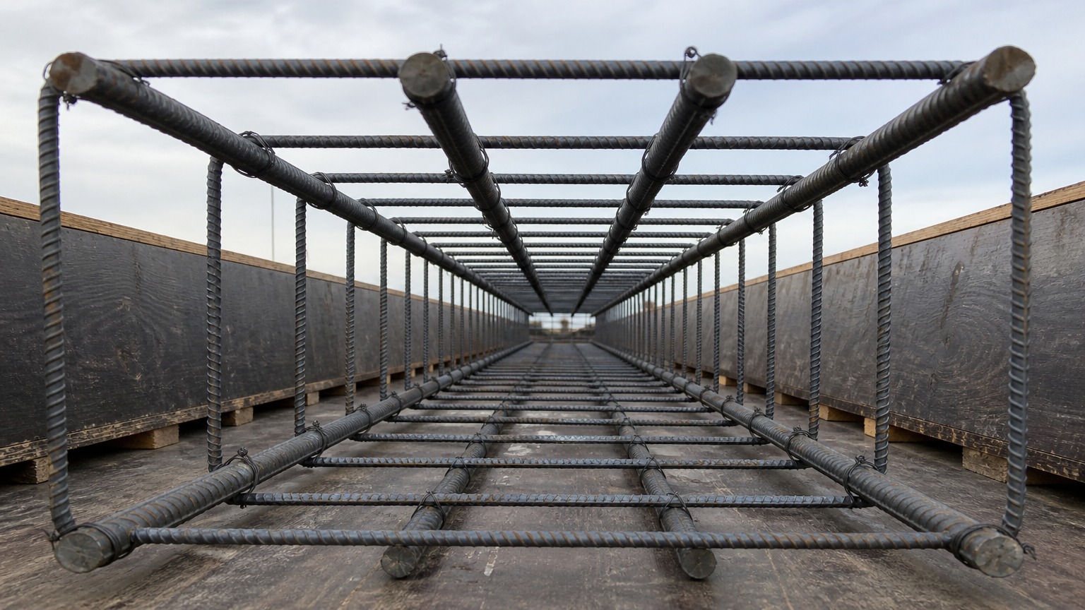
Conclusion: lap splice length is a diameter multiple fixed by the design code, not by habit — confirm the code, the grade and the concrete, then measure every lap before the pour.